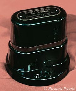
The circular base of the cell is 4 3/16" dia. and the cell is 3 7/8" high. There is a metal tag on the top of the cell which reads: WESTON STANDARD CELL / MODEL 4 NO. 19866 / WESTON INSTS., DIV. OF DAYSTROM, INC., / NEWARK, N.J., U.S.A. There is a decal under the cell: Dec. 21 '59. Includes National Bureau of Standards Certificate, (80k) dated March 1, 1960, and Weston Instruments Certificate, (132k) dated February 26, 1960 for this cell: number 19866. (Humboldt College decal: 30642, now removed.)
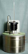
The instrument stands (under construction). Serial numbers and ID numbers can be seen in an image of the Manufacturer label and HSU tags.
An instruction and description sheets from the manufacturer is available as scans.
A Micro-Set thermoregulator, described as catalog number 61847 in the BKH Catalog 69 Scientific Apparatus instruments and supplies for: Industrial, Educational, Clinical and Research Laboratories. San Francisco (1968) p 1021 is used to set the temperature.
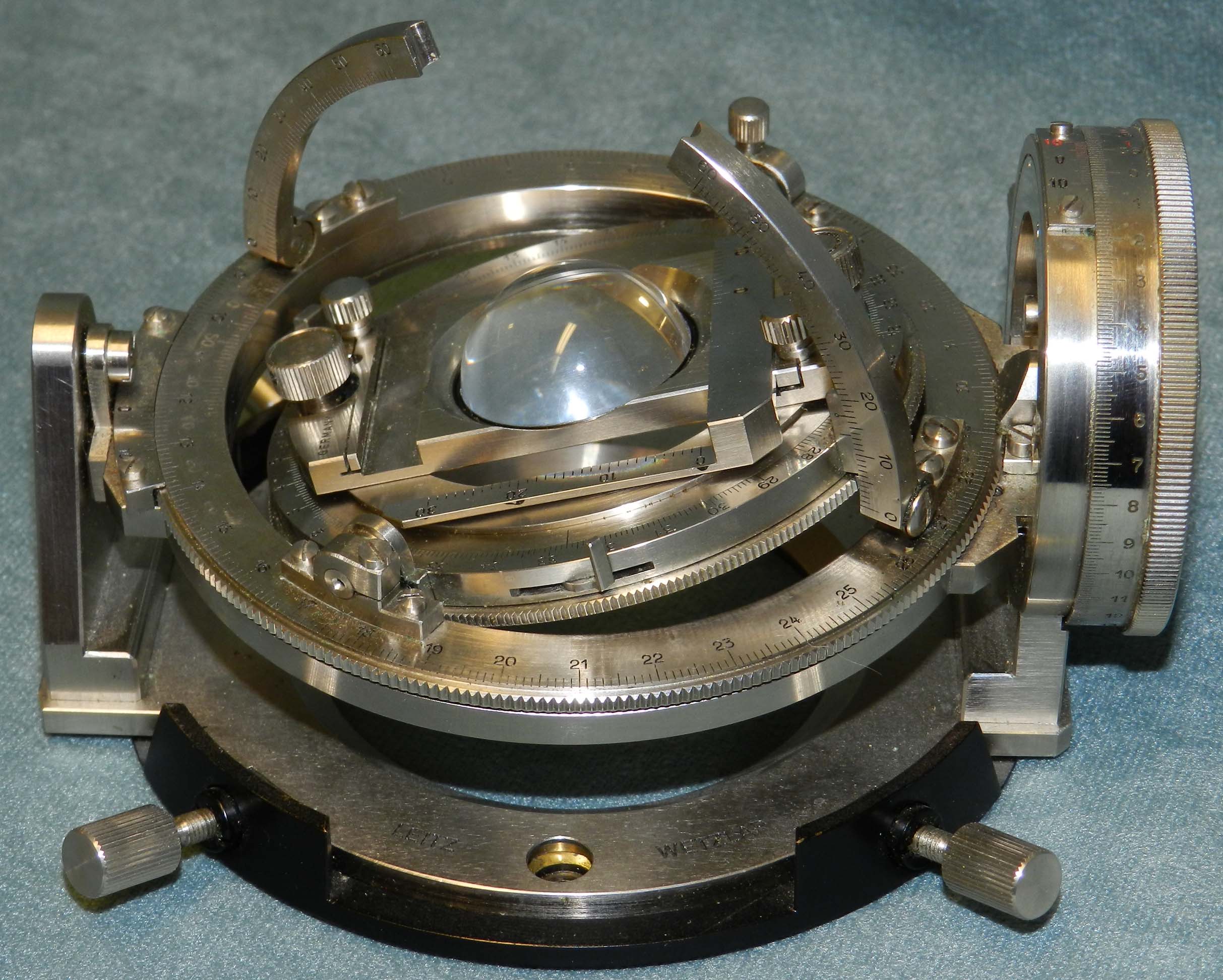
A photo of the stage with accessory hemispheres can be seen here . The stage came in a fitted XX" x XX" x XX" mahogony box. The box exterior can be seen here , while the open box with the stage and accessories exposed can be seen here .
The instrument ( under construction ). Micro-Set thermoregulators, described as catalog number 61847 in the BKH Catalog 69 Scientific Apparatus instruments and supplies for: Industrial, Educational, Clinical and Research Laboratories. San Francisco (1968) p 1021 are used to set the temperature to a precision of ±0.01°C. An instruction and description sheets from the manufacturer is available as scans .
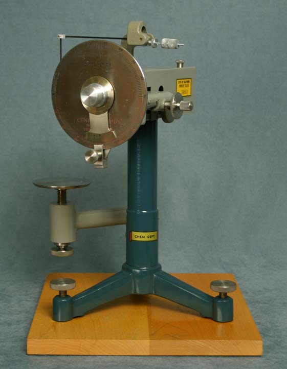
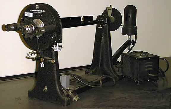
The instrument is built around a heavy cast-iron stand. It is described in detail in the Cenco catalog description . The instrument on display is in very good condition, with some light surface corrosion of galvanized(?) parts. The instrument came in its original metal case, and is accompanied by two tensiometer rings in their original containers. One is mounted on the instrument for display. You may view a scan of the catalog description of a similar ring with a hook instead of rod attachment You may view an image of the case exterior , an image of the instrument and accesories in the case , and photo images of the two ring containers , open and closed. The container labels are identical in dates, specifications, and inspector. The ring is seen in the open container (arrow, the lower metal retaining ring is part of the box ).
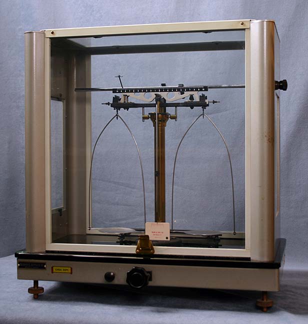
The analytical balance is the most fundamental tool in the chemists arsenal. It is used to determine the masses of, or in other words the amount of stuff in, objects or samples. The balance is a comparison instrument. It compares standard or known weights placed on the left-hand pan to unknown samples or objects placed on the right-hand pan. The current instrument also has a rider (a 10 mg bent wire weight which is moved along the graduated scale on the top of the beam) to measure small (1-10 mg) differences in mass. The glass case is to protect the balance from drafts while samples are being weighed, as well to keep the delicate mechanisms free from dirt. The scanned catalog description is from the 1958 Fisher Scientific Company catalog, Modern Laboratory Appliances, Catalog 59.
This balance was probably used in analytical chemistry in the basement of Founder's Hall1. It was later used in the student research lab (Science A 460) until the building remodel in 1988 when it was placed in storage. It appears to be the only Voland balance kept in Chemistry when the department replaced the department's two-pan balances for instructional laboratories with the purchase of Mettler H10 balances in 1971.
According to MacNevin, Voland and Sons was established in 1888 in New Rochelle, N.Y.
Early descriptions of the balance and its use are provided below:
Krayer. Use and Care of a Balance. (1913)
Smith. "Weighing" in ...QUANTITATIVE CHEMICAL ANALYSIS ... (1921)
Description
The balance is in excellent, working condition. Finish, dimensions etc. are well described in the catalog scan. Voland riders in small plastic boxes with two different styles of labels are in the collection. Both were held in the Chemistry department. The linked image of the first rider box shows the weight hand written, while the linked image of the second rider box shows the weight value typed. There is a yellow property decal: STATE OF CALIFORNIA / HUMBOLDT COLLEGE / 15137.
Directions for setting up this balance accompany this specimen and can be seen in the linked scans (three sets of instructions, for serials M17304, M17305 and M17699, were stored together in the file drawer in the analytical chemistry prep room).
References
MacNevin, William Marshall, The Analytical Balance, Its Care and Use, Handbook Publishers, Inc., Sandusky, Ohio, (1951), pg. xi.
Shannon, John M. and Geraldine C. Shannon. The Assay Balance: Its Evolution and the Histories of the Companies That Made Them. (privately printed,1999).
1 This use is inferred from the storage of three sets of Voland 200 directions in the analytical chemistry service room in Science A (2007).
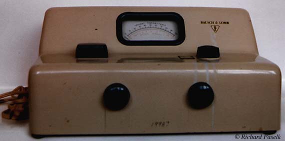
The instrument case is of die-cast metal with a cream-colored enamel finish. It is 14 1/2" x 10 3/4" x 7" high. The trim and control knobs are in a dark green plastic. The 3 3/4" meter has a mirrored scale graduated from 0-100% by 1% and from 0-infinite Optical Density (logarithmic scale in red). The wavelength scale, stamped on a brushed aluminum disk visible through a window below the meter, is graduated from 350-1000 nm by 5 nm with numbered major divisions every 25 nm. There is a yellow decal on the column: STATE OF CALIFORNIA / HUMBOLDT COLLEGE / 19987. The serial number (HB 2.072) and model number (33-29-40) are given on an aluminum tag on the rear of the instrument. With the exception of some staining on the case, the instrument is in very good, operating condition.
The Chemistry department has a number of operating/reference manuals, a scan of the 1959 edition is linked.
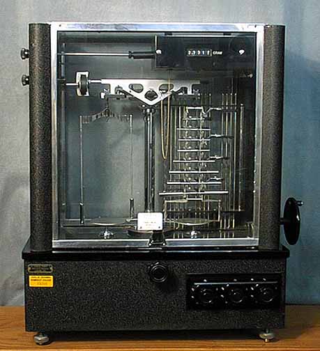
This is Voland's top-of-the-line analytical balance. The aluminum case is black crinkle finished with chromium plated and aluminum trim. There are glass panels on the front, rear, and top. The plate is black glass setting on a sheet aluminum base.The case is 20 1/2"h x 17 "w x 10"d. The balance has stainless steel pans on chrome-plated, 3-piece, hangers. The column is polished chrome-plate, other interior parts are chrome-plate or polished stainless steel. The weights (Class S) are either aluminum or stainless steel, and may be added to give any combination from 0.1 - 99.1 gram. An additional 100 g weight in the case allows a total of 199.9 g to be added to the right pan/hanger. The chainweight allows addition of 0.0000 - 0.1000 by turning a dial which has a mechanical counter readout. A knob on the left side of the case enables zeroing of the balance via a second adjustment of the chain. A blue eneameled aluminum tag with raised metal letters and fields is rited to the right side: VOLAND & SONS INC. / NEW ROCHELLE, N. Y. / MODEL NO. 750-D / SERIAL NO. M 17844 . There is a yellow decal on the front: STATE OF CALIFORNIA / HUMBOLDT COLLEGE / 15201. According to HSU inventory this balance was purchased in March of 1957.
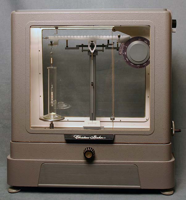
The aluminum case is gray crinkle finished with nickel plated (now corroded on the outside) trim. There are glass panels on the front and top, with a translucent opal glass panel on the back. The plate is black glass setting on a cast aluminum base. The case is 20"h x 18 1/4"w x 9"d. The balance includes a two gram plummet, calibrated at 20° C, shown in the close-up digital image , with a built-in thermometer with a range of 10°-30° C. There is also a ungraduated glass cylinder, as seen in the close-up image . A small cardboard box (3 5/8" x 2 5/8" x 7/8") originally containing the chains for this balance was found in the balance drawer. See catalog description for additional details . (Property tag: State of California/ 43910) More information on this and other balances is available on the Chemical Balance at Humboldt pages accessed via the link below. 1 According to the equipment inventory list for HSU this balance was acquired in 1959.
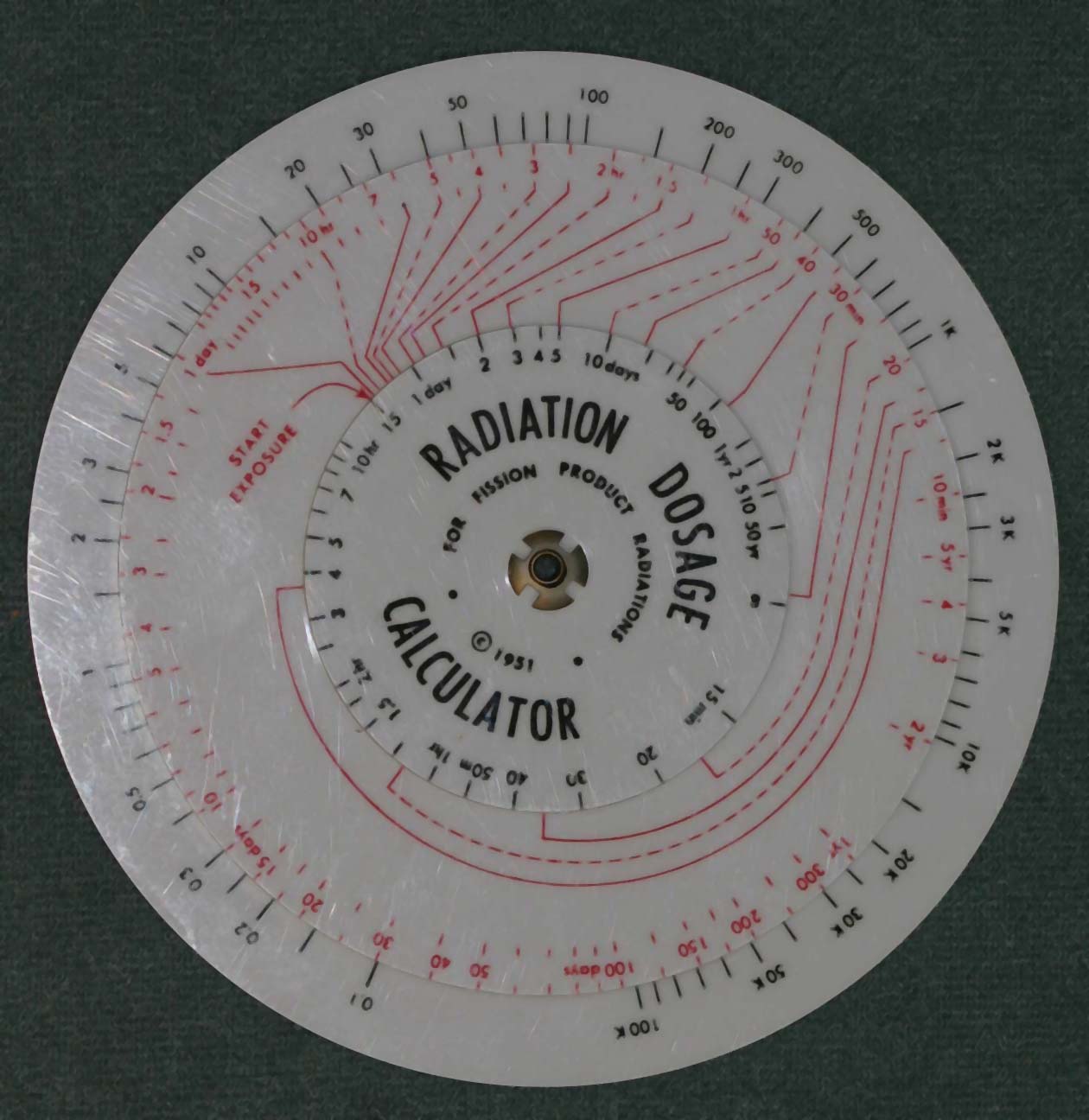
The slide rule is constructed of a 4.5" main disk of plastic with two smaller disks stacked on the front face allowing free rotation of each relative to the others. There is no cursor. Operating instuctions are provided on the reverse, as seen in this photo . A similar rule, in aluminum, from Eugene Dietzgen is described in the catalog description above, from: Eugene Dietzgen Co. Dietzgen, Seveteenth Edition General Catalog . Chicago, (1955).
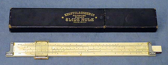
10" "Polyphase Duplex" slide rule (mahogany & white celluloid), <1934: DF, CF, CIF, C, and D scales on front; K, A, B, S, T, CI, D, and L scales on back. There is a double sided sliding glass cursor held in a metal frame to celluloid sliders. The upper and lower parts of the rule body are led together with nickel-silver brackets riveted to the lower section, and clamped with a screw to the upper. The rule is inscribed(red filled) / PAT. JUNE 5, '00 / DEC. 22.'08 on the front upper (clamped) face and KEUFFEL & ESSER CO. N.Y. on the front lower (riveted) face. KEUFFEL & ESSER CO. is stamped on the upper cursor slider, and PATENT 2,086,502 (for the sliding cursor) is stamped on the lower cursor slider in black. The model number <4088-3> is stamped in red at and parallel to the left end of the slide. There is no serial number. The original leatherette covered cardboard case is included.
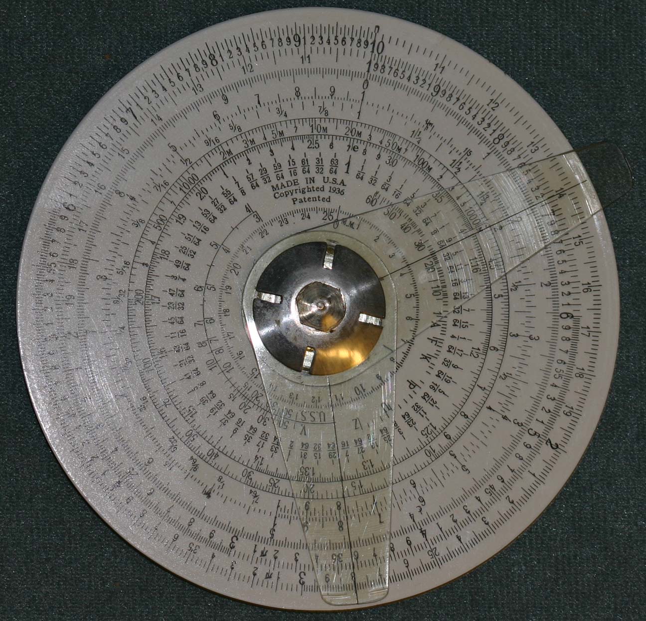
The slide rule is constructed of a single 4.25" disk of plastic (celluloid?), graduated on both sides. There is a dual cursor on the obverse (the cursors have a friction fit and may be adjusted relative to each other then rotated as a unit) and a single cursor on the reverse, as seen in this photo . A similar rule, in aluminum, from Eugene Dietzgen is described in the catalog description above, from: Eugene Dietzgen Co. Dietzgen, Seveteenth Edition General Catalog . Chicago, (1955).
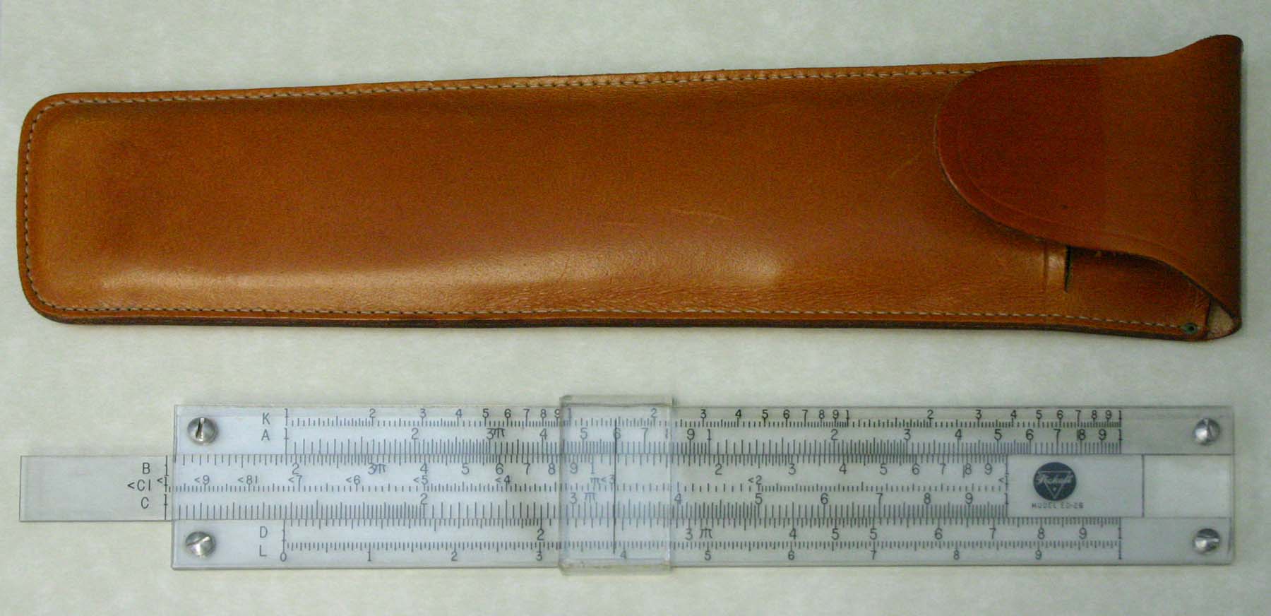
The body of the rule is 9" long. It is made from three layers of clear plastic (perspex) with the slide fitting between the top and bottom layers and the upper and lower segments of the central layer. The three layers are held together with aluminum screws at each corner. A separate clear plastic cursor slides in two groove formed between the top and bottom layers. It is accompanied by its original leather case.
The basic history of the slide rule is outlined in Michael R. Williams, A History of Computing Technology, Prentice-Hall, Inc., 1985, pp. 111-118 and John P. Ellis, The Theory and Operation of the Slide Rule, Dover Pub. Inc., New York, 1961, pp. 247-250. An extensive history of the slide rule is found in A History of the Logarithmic Slide Rule and Allied Instruments by Florian Cajori, The Engineering News Publishing Co., New York (1909) [recently reprinted].The patent number corresponds to 1937, thus 1937 is the earliest possible date for this rule. Two more recent and excellent treatises are the books by Dieter von Jezierski, Slide Rules: A Journey Through Three Centurie, Astragal Press, Mendham (2000), and Peter M. Hopp, Slide Rules: Their History, Models, and Makers, Astragal Press, Mendham (1999).
* According to Hopp (1999, p210), the Pickett ED-26 projection rule was made by Projection Optics Company, Inc.
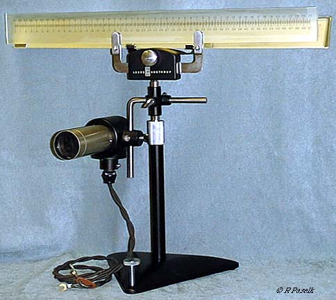
The heavy, cast iron, triangular base has a single chromed-brass, knurled, leveling screw on the front point. The base holds a single half inch rod vertically in a heavy sleeve, clamped with a knurled sleeve and collet. The lamp housing is of cast heavy aluminum construction with a chromed thumbscrew clamp holding it onto a bent rod which in turn is clamped to the tripod base with a black painted brass right angle clamp. The lens holder of the lamp is constructed of chromed brass sleeve with a double convex lens at the end, which slides over a second tube for focusing.
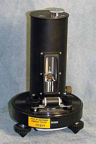
The instrument is 9" high with the base 5" in diameter. This particular instrument has a flat-black finish on the aluminum case, a heavy Bakelite base, and a chrome-plated knurled head for the clamping and adjusting shafts. A 70,000 Ohm critical damping shunt resistor is in place across the input. The mirror in this instrument is 3/8" dia, as opposed to the 1/2" mirror in the lowere sensitivity instruments described in the Cenco catalogs below. The serial number, 55953, is engraved in white on the front of the base below the window. A white plastic oval tag folds out from beneath the serial number on the base with specifications handwritten in for this instrument: SENS. .00003 uA/MM C.D.R.X. 70000 [ohms] PERIOD 23.5 Sec RESIS. 831 [ohms] CAT. NO. 2285F There is a yellow decal on the base: STATE OF CALIFORNIA/ HUMBOLDT COLLEGE / 30408. A No. 2178 Prism by L&N used in the P-Chem lab is in storage. Research A similar instrument (Type R) is illustrated and described on p736 of the Cenco 1960 Catalog (J-300) and on p 1275 of the 1950 Cenco Catalog (J150).
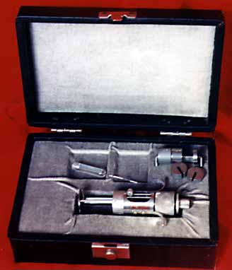
The sampler consists of a stainless steel framework which holds a precision bore glass sample tube with needle on one end. The body of the framework holds and constrains the movement of a teflon tipped plunger which fits into the glass tube. the delivery volume is adjusted by changing the degree of travel of the plunger. The travel is calibrated with the aid of six precision ground ss spacers (stamped .05, .04, .02; with the smallest, 0.01 and 0.005, unmarked), which fit along the exposed shaft of the plunger shaft. The instrument is adjusted by placing one or more spacers on the shaft, and then tightening the clamp riding in the center of the framework. The device is housed in a black leatherette coverd box (7.5" x 5" x 2.25") with faded blue velvet lining.
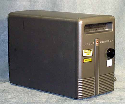
The pointer galvanometer is a sensitive instrument for measuring current. It consists of a magnet coil with an attached needle suspended between the poles of a magnet. When an electric current is introduced into the magnet coil it induces a magnetic field, causing the coil to rotate in proportion to the current. The example here is a null instrument, that is it is designed to be used in circuits where two currents are balanced against each other, i.e. with a Potentiometer or a Wheatstone Bridge, until the meter reads zero.
Some contemporary/early descriptions of the Galvanometer and its use are provided below:
Moving-Coil Galvanometer Kimball, A College Text-Book of Physics (1923)
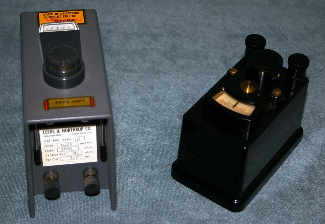
The instruments are described in detail on two Cenco catalog descriptions. For the 1960 galvanometer a scan of the description from the Cenco. Cat J-300, General Catalog Laboratory Apparatus & Scientific Instruments , Chicago. (1960?), is shown . For the pre-1960 galvanometer a scan of the description from the Cenco. Cat J- 150 General Catalog Laboratory Apparatus & Scientific Instruments , Chicago, (1950) is shown .
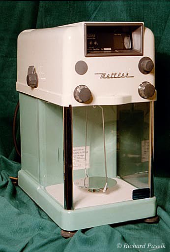
The balance case, of molded plastic with an aluminum base-plate, is 15 3/4" high, 8 1/4" wide and 13 3/8" deepThe balance has a capacity 160 g., a range of 1200 mg on the optical scale, an accuracy of ±0.1 mg, and weights adjusted to within Class S tolerances. The balance on display is set up with a special Mettler clear plastic demonstration top to allow students to see the inner workings. The chemistry department had a single balance set up in this fashion which would be moved to various labs when introducing the use of the Mettler balance. Three views of this balance are provided: Mettler demonstration balance, right-side view ; Mettler demonstration balance, left-side view ; Mettler demonstration balance, top view . A folder included with the balance contained the following: Mettler (brochure listing Mettler Analytical, Multi-purpose and Precision balances), Test Test Test (brochure on weighing errors), unpacking/setting-up card, annual service agreement card, Xerox sheets detailing balance tables , and two brochures: Mettler, Multi-Purpose Balances Directions for Use (brochure) , Mettler Service (brochure) . The chemistry department also had a number of posters showing the features of the Mettler balance. A scan of the remaining 24" x 36" poster featuring the Mettler H10 is displayed.
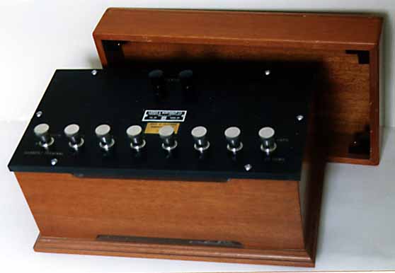
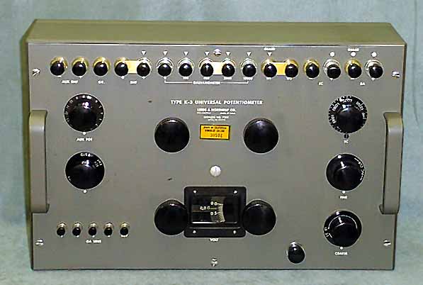
There are two Bakelite terminals at the upper center of the top panel labeled "Potentiometer" with the left one also labeled "A." Eight nickel plated brass terminals are arranged across the bottom of the panel labeled: "COMMON/A/CURRENT TERMINAL; 7.5/.2; 3/.5; 1.5/1; .75/2; .3/5; .15/10; .075 AMPS/20 OHMS." The panel is held to the case with six chrome plated brass slot-head screws. The instrument has a 6 1/2 x 12 1/2" satin Bakelite top-plate, and a polished solid mahogany case and cover. It is 6" high to the top of the Bakelite plate. The case has air circulation slots at the bottom and top of the front and back panels for air circulation, as well as 32 half inch holes in the bottom of the case. There are four rubber feet which hold the case about a half inch above the ground. Condition: excellent. There is a decal on the top plate: State of California Humboldt College 30248.
The reflecting galvanometer is a sensitive instrument for measuring current. It consists of a magnet coil with an attached mirror suspended between the poles of a magnet by a thin gold ribbon above and a coiled gold wire below. When an electric current is introduced into the magnet coil it induces a magnetic field, causing the coil to rotate in proportion to the current. The mirror allows the user to see very small deflections, and thus to measure very small currents, by observing a distant reflected scale. In this instrument an illuminated image of a line is projected through a small telescope onto the mirror, which reflects it onto the built-in scale on the ground glass window on the front of the case.
The potentiometer is used to measure voltages by comparison to a known reference voltage. The L&N K-3 universal potentiometer was the top-of-the-line research grade instrument used in industrial and university labs for best quality work. Prior to the development of digital electronics potentiometers were the standard for sensitive and precise voltage measurements required for measureing temperature, pH, conductivity, etc.
The current instrument is composed of a series of precision resistors which may be placed in series with a precision slide-wire resistor to create a resistance of known value. In use the instrument is connected to known and unknown voltage sources, and the resistors are adjusted until the voltages are matched as indicated by a null reading on a sensitive galvanometer. The instrument is also set-up so that the known source may be readily calibrated against a reference voltage source (generally a Weston standard cell). The potentiometer made up the heart of a great number of instruments for measuring such quantities as pH, conductivity, light intensity etc.
Some contemporary/early descriptions of the potentiometer and its use are provided below:
The Potentiometer Duff, A. Wilmer. A Text-Book of Physics (1921)
Hydrogen-Ion Determination Braun Corporation. Catalog No. 34 (1934)
Conductivity Braun Corporation. Catalog No. 34 (1934)
The instrument on display is in excellent, like-new condition. It is described in detail in the Cenco catalog description. The instrument is accompanied by an operating manual that is not on display, but may be viewed by clicking here.
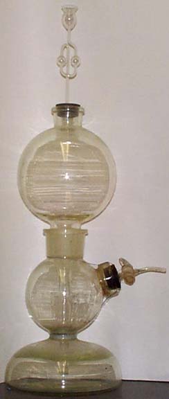
The apparatus is 63 cm high to the top-lip of the upper bulb, 86 cm to the top of the thistle-tube. The base is 27 cm in diameter. The upper and lower bulbs connect through a 71/60 standard taper joint (etched in middle bulb). EXAX / USA is etched into the center of the upper bulb in small (4 / 2 mm) letters. This apparatus has a nominal capacity of 2,000 mL. The glass has a light yellow-green tinge to it, and tool marks are quite obvious on the apparatus, especially on heavy lips of the two stoppered orifices. The Stopcock is Kimax with a #4 standard taper plug. The thistle tube is etched KIMAX USA on the funnel-bulb.
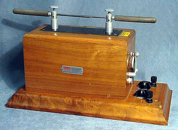
Used as a demonstration tool in physics and chemistry and as an arc source for demonstrations etc. According to Wikipedia,
"An induction coil or "spark coil" (archaically known as an inductorium or Ruhmkorff coil after Heinrich Ruhmkorff) is a type of disruptive discharge coil. It is a type of electrical transformer used to produce high-voltage pulses from a low-voltage direct current (DC) supply. To create the flux changes necessary to induce voltage in the secondary, the direct current in the primary is repeatedly interrupted by a vibrating mechanical contact called an interrupter. Developed beginning in 1836 by Nicholas Callan and others, the induction coil was the first type of transformer. They were widely used in x-ray machines and spark-gap radio transmitters from the 1880s to the 1920s. Today their only use is as the ignition coils in internal combustion engines, and in physics education to demonstrate induction." ("Induction Coil", Wikipedia; http://en.wikipedia.org/wiki/Induction_coil; downloaded 6/28/2012)